I’ve been trying to find good information to post in this “misc.” category and I thought that I would share these photos. They are of the modified toaster oven that Jess Oliver uses when repotting single transformers. If I thought I was going to be repotting many transformers in the future I think I would try to find an old toaster oven and do the same. It would be better than having to clean up my real oven if I ever dripped some of the melted compound (again)!
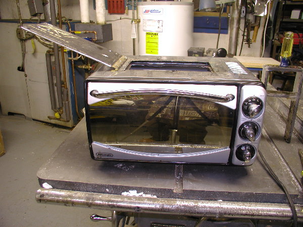
Modified toaster oven
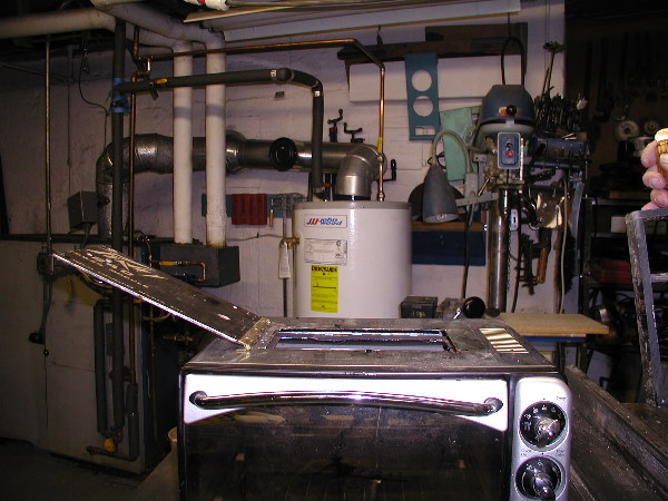
Ready to begin
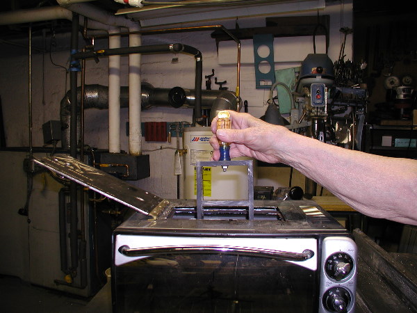
Lowering transformer into oven
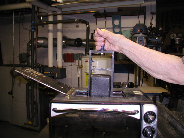
Removing the transformer can
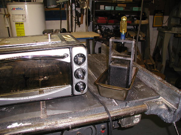
The finished can
I forgot I had this – it’s a 1965 B15NF schematic that I redrew. It’s pretty much the same as the 1966 version I posted previously. However, I did notice some differences with the speaker cable wiring, as well as the Treble pot on channel 1 being shown as 4 Meg, instead of 1 Meg. That seems odd to me, but who knows? There may be other subtle differences that I didn’t catch. I’ve included a photo of the preamp section of the schematic that I used as a reference.
B15NF Schematic 9/65 (PDF)
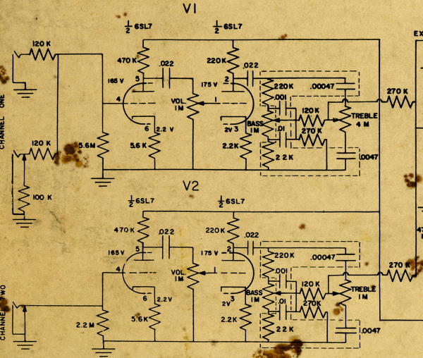
9-65 B15NF preamp schematic
I finally got around to redrawing my B15NC schematics, something that I have been wanting to do for quite awhile. I have redrawn 3 different versions of the NC schematic, which are shown here. These drawings are based on originals that I have, and I have tried to replicate the original’s appearance as closely as I could.
The first is dated 1/64. This is an early NC schematic and does not have circuit voltages shown on it yet.
B15NC Schematic 1/64 (PDF)
The second is dated 11/64. It has various voltages shown in the circuit, and there have been a few capacitor additions and deletions.
B15NC Schematic 11/64 (PDF)
The third is dated 9/64. It is the same as the 11/64 schematic except for the center tap on the hum control pot. Rather than attaching to point “K”, this symbol has been marked over by hand and changed to a ground symbol.
B15NC Schematic 9/64 (PDF)
Because of the size of the original schematics, these drawings are formatted to be printed on 8.5″ x 14″ paper. When printed, they should be the size of the originals, as long as no resizing occurs within Adobe Acrobat.
The new power resistors arrived today and I swapped them out with the ones I originally had on the board.
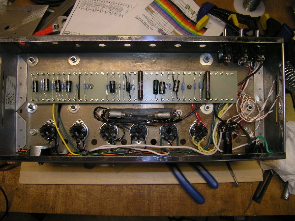
New Ohmite power resistors
It may seem like a silly detail but I am so much happier with how the new ones look. The previous ones had been bothering me ever since I put them in.
(edit: I just had to replace the new 1K resistor with another new one. I just double checked it with a meter and it read about 10M to begin with, and kept climbing the longer I kept the test leads on it. I’m pretty sure I checked it before installing it, so I guess I damaged it while soldering it. I was extra careful with heat-sinking the leads on the latest one and it seems fine)
Here is a drawing I did of the eyelet board in my B15NC. It just shows the components on the board; it does not show any of the control wires, etc. that also connect to it.
1964 B15NC Eyelet Board (PDF)
I finally got the output transformer potted and then remounted onto the chassis. The 3 primary leads were too short so I had to extend them. I also soldered leads to the multi-cap and just curled them up for now. With that done I installed the fuse holder and finished wiring the power supply.
Before going much further I needed to get the 2 logo lamps installed so that any future wiring could be routed around them. Since this started out as a B15NF, the lamp holders were different from what was used in the B15NC. These holders were originally mounted to the larger B15NF printed circuit board. Since I am using a turret board that is much smaller, I had to find a different method for attaching the holders. A couple of new holes and some #4-40 machine screws took care of that. I also installed a new rubber light shield over the logo slot, since the original had come loose and was in poor shape.
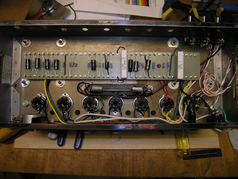
The chassis gets a little more crowded
This was intended to be a learning experience for me and so far it has been. I look at what I’ve done so far and sometimes see things that I wish I had done better. There have been a couple of things already that I have gone back and changed. The key has been whether I thought I could perform the change without ultimately making things worse. One thing that has been bothering me for quite awhile are the (2) 10W resistors – they are larger than what I was expecting and I have never been happy with how they look on the board. I will be replacing them with shorter ones which should arrive later this week.
Well, I came close to getting all the components soldered to the turret board today. Unfortunately, I miscounted and did not order enough .022 mf capacitors (needed 7, ordered 6). For this project I decided to go with slightly higher quality components, so I was using Solen fast caps for all but the electrolytics (which are Sprague Atoms). I have other caps here that I could pull from but I really don’t want to mix brands. I’ll just have to wait until I get the last one in. That’s what I get for not ordering a few extra to begin with!
Here’s what the board looks like with everything except the one missing cap:
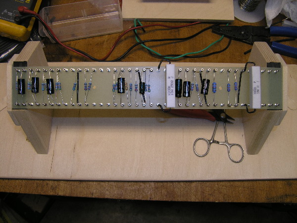
New turret board w/components
For comparison, here is the board on a 1964 B15NC:
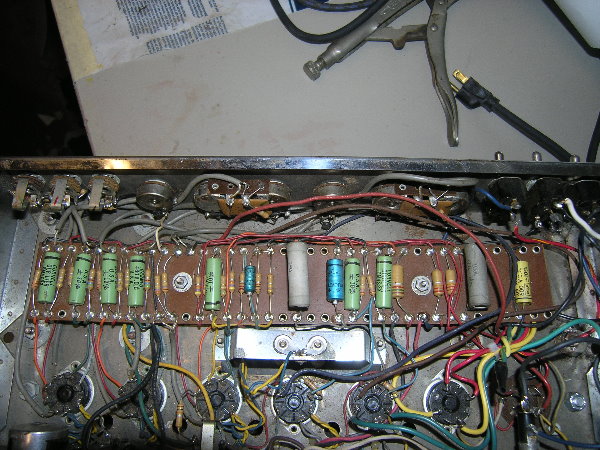
1964 B15NC eyelet board
I am close to the point where I need to start installing components on to the new turret board. Before I do, I thought I would show a photo of the board while it is still nice and untouched. It is made from 1/8″ thick G10/FR4 board, so it feels nice and strong. This was my first time making a board and I’m really pleased with how it turned out.
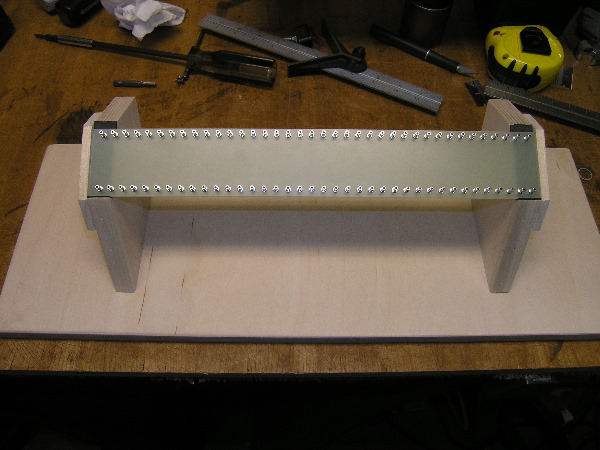
New turret board
I got a little more of the power transformer wiring done tonight, including partially wiring the switches, as well as the power cord socket. I also made some improvements to the wiring I had done previously.
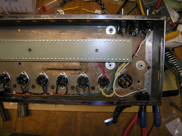
Additional power supply wiring


