Output transformer, etc.
I finally got the output transformer potted and then remounted onto the chassis. The 3 primary leads were too short so I had to extend them. I also soldered leads to the multi-cap and just curled them up for now. With that done I installed the fuse holder and finished wiring the power supply.
Before going much further I needed to get the 2 logo lamps installed so that any future wiring could be routed around them. Since this started out as a B15NF, the lamp holders were different from what was used in the B15NC. These holders were originally mounted to the larger B15NF printed circuit board. Since I am using a turret board that is much smaller, I had to find a different method for attaching the holders. A couple of new holes and some #4-40 machine screws took care of that. I also installed a new rubber light shield over the logo slot, since the original had come loose and was in poor shape.
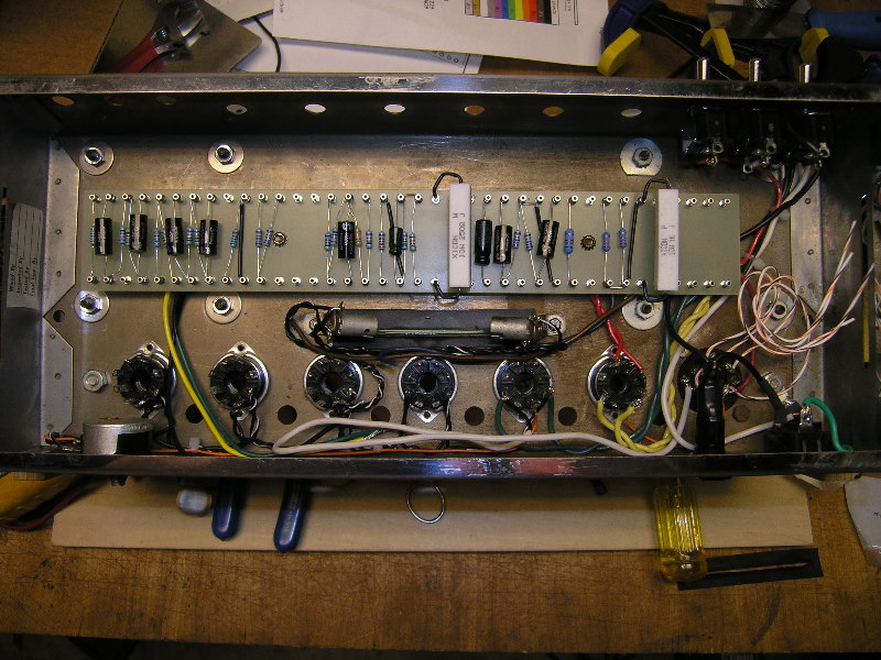
This was intended to be a learning experience for me and so far it has been. I look at what I’ve done so far and sometimes see things that I wish I had done better. There have been a couple of things already that I have gone back and changed. The key has been whether I thought I could perform the change without ultimately making things worse. One thing that has been bothering me for quite awhile are the (2) 10W resistors – they are larger than what I was expecting and I have never been happy with how they look on the board. I will be replacing them with shorter ones which should arrive later this week.

Hi.
Excellent work. I also have a 1966 B15NF according to the serial number. I was wondering where you found the turret board or did you build it yourself?
the chassis I have didnt come with any transformers, so I substituted Hammond for both.
would like to locate a circuit board like the one you have.
These are outstanding little amplifiers. been having a lot of fun working with the one I have.
I used shielded Tefzel wire( stranded 22ga.) for the interconnects of signal inputs.
Cheers,
Ed
Ed,
I made the board myself. I got a 2” x 24” piece of .125”, G10/FR4 Garolite from McMaster-Carr (#8557K13) and cut it down to 13”. The turrets are Keystone brand and I got them from Mouser (#534-1549-4). I had never made a board before and I’m really happy with how this one turned out. I’m lucky, in that I work with AutoCAD every day, so I was able to draw and print a full-scale layout of the turrets. I used spray adhesive to temporarily attach the layout to the board and used a 3/32” bit to drill the holes. I have a drill press, so I clamped a fence to the table to keep the holes spaced evenly from the edge of the board and all I had to do was keep sliding the board sideways as I went from hole to hole. I did find out that you really need to keep a firm grip on the board so that it doesn’t try to lift when the bit is being pulled back out. If the bit catches like that and lifts the board at an angle it can end up making an oblong hole.