September 30th, 2009
Mark
I got a modest start on the power supply tonight. I installed the newly potted power transformer, as well as the new multi-cap can and 3 new switches. I got the 5v and 6.3v heater wires, and the power transformer secondary wires connected to the tube sockets. I temporarily mounted the new turret board, in order to get the transformer leads run in an orderly manor.
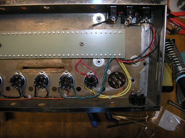
Heater and secondary leads connected
My next step will be to wire the primary side of the transformer. I will hold off wiring-in the fuse holder until I have everything wired to the cap can, since that’s easier to do with the fuse holder out of the way.
September 29th, 2009
Mark
This is a service manual for the B12XT and B18X Portaflex amplifiers. I have redrawn it from a photocopy and have tried to match the look of the original as best as I could.
B12XT/B18X Service Manual (PDF)
September 29th, 2009
Mark
Here is a schematic of an Ampeg B15NF, dated 1-66. I redrew it from an original I have and tried to closely match its appearance.
B15NF, 1-66 (PDF)
September 29th, 2009
Mark
Here are some schematics I have for the Oliver P502. I realize that this is not a Portaflex amp, or even an Ampeg amp. However, since it was Jess’ new twist on his original Portaflex concept (after starting his own company), I think it’s appropriate that it’s included. The first file is a schematic of the amplifier itself. I redrew it from a photocopy but tried to closely match the appearance of the original.
P502 Schematic (PDF)
The second is a schematic of the cabinet wiring.
P502 Cabinet Wiring Schematic (PDF)
The third is more of a logical diagram of the cabinet wiring and is meant to more closely resemble what is actually seen inside the cabinet. Please note that the wire colors shown are based on the wiring of my particular cabinet, and may not match others. According to Jess Oliver there was not a strict color-code followed when wiring the cabinets.
P502 Cabinet Wiring Diagram (PDF)
(Update, 12/18/09 – I just realized that the P502 Cabinet Wiring Diagram PDF that was posted here was incorrect. It was a duplicate of the P502 Cabinet Wiring Schematic. The correct file is now posted)
September 29th, 2009
Mark
The shock mounts that Ampeg used to use were manufactured by Lord (they are referred to as “plateform mounts” in Lord’s literature). The model that Ampeg used was 100PDL-8. Lord’s product literature has not included this part number for several years, but it is still produced. If you are not wanting to buy in quantity it’s much easier to just get them from Fliptops.net. I believe they are also available from Vintage Amp Restoration, but I haven’t confirmed that.
Another option is to get something similar from McMaster-Carr. They carry a similar model shock mount from Lord, p/n 6008K61. This is Lord’s model 100PL-8. The only difference between it and the mount that Ampeg used is that it has a square base rather than the diamond base. They can be used just as they are, or you can file/grind down 2 of the corners to make them look like the originals. I haven’t tried this yet but it should not be too difficult since the base is aluminum.
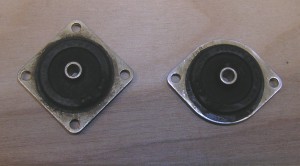
Shock mount comparison
September 29th, 2009
Mark
I have set up this category to be a bit of a catch-all location for miscellaneous information that I don’t think falls within another category. I hope I have a few useful things to post here!
September 29th, 2009
Mark
I got my potting compound yesterday, so I got the new power transformer potted. It took more compound than I anticipated so I held off on potting the output transformer. Once I have more compound I will pot it too. I am using Hammond transformers: a P-T274BX power transformer and a P-T1650G output transformer.
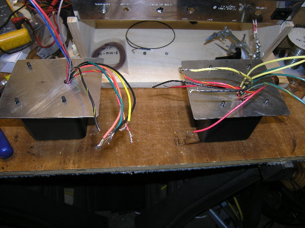
Transformers w/temporary base plates
I decided to try something new while potting these transformers. I wanted to be sure that the transformer leads were bundled and properly positioned during the potting process so that they would line up with the holes in the amp chassis. To do this I took two pieces of 1/16” aluminum and drilled holes in them to match the holes in the chassis. This allows me to pull the leads through the large hole and attach the aluminum plate to the transformer can, thereby ensuring that the leads are properly positioned while the compound sets up. It seems to have worked fine on the power transformer so I’m sure it will work okay on the output transformer as well.
I’m looking forward to getting the power transformer installed so I can start working on wiring the power supply.
September 28th, 2009
Mark
This amp came with just the output transformer; the power transformer was missing. Due to the overall condition of the amp, I was not comfortable trying to reuse the existing output transformer, plus the wires looked to be in pretty bad shape. That meant I would need to remove the OT from its can so that I could repot a new one in it. Fortunately, I also have a spare can here that I will be able to use for a new PT.
I had un-potted a power transformer about a year ago. While it was somewhat messy, not to mention smelly, it wasn’t too bad of a process. Removing this OT from its can proved to be more difficult, however. Since the OT is smaller than the PT, the transformer had small blocks of wood wedged on 2 sides to keep it centered in the can.
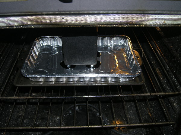
Melting potting compound in oven
This made the transformer much more difficult to remove, since it did not just drop out like I expected. Once I discovered the blocks of wood, I was able to pull them out with a pair of pliers. This allowed the transformer to drop out as I had been expecting it to, but not before I had created a bit of a mess with the liquefied (and extremely hot!) potting compound.
I cleaned up the 2 empty cans and decided that this would be a good time to give them a fresh coat of paint. I had originally planned on using a black, crinkle finish paint but then I saw something different at Home Depot. It was a black, textured-finish paint from Rust-Oleum (7220 Black), so I decided to give it a try. I was very pleased with the results! To my eye the texture matches the original, subtle texture of the cans quite well. I’d like to be able to use it on the tube cage too, but I’m afraid it wouldn’t hold up well with the heat from the tubes.
Everything is now ready for re-potting the transformers; I’m just waiting on new potting compound, which should be arriving today.
September 28th, 2009
Mark
I got a modest start on the wiring by wiring the heater circuit and hum control pot. After seeing photos of other people’s work I had pretty high aesthetic aspirations for my wiring. I used solid, continuous buss wire to daisy-chain the sockets together, slipping Teflon tubing over the wire between sockets for insulation. I found the combination of stiff wire and cramped space to be tougher to work with than I thought. The end result looks okay but I was really hoping for better. I did start improving toward the end, so I’m hoping to get better as I gain experience.
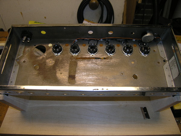
Heater & hum control wiring
Rebuilding the power supply seems like the next logical step, so I’ll need to get my power transformer ready.
September 27th, 2009
Mark
Gutting the chassis was fairly straight forward. Everything that I planned on reusing was placed in plastic bags and labeled. This included items such as the control packets, hum control pot, 1/4″ jacks, etc. The switches looked pretty rough so I’ll be replacing them with the correct models from Carling. Since this was originally a B15NF, it utilized a printed circuit board. As such, the tube socket tabs were bent over and soldered to the board. Several of the tube socket tabs had become brittle, which caused them to break while desoldering them from the board. Although I hadn’t anticipated this, it turned out to be a good thing. This forced me to replace all of the sockets with matching NOS sockets. In addition to installing new tube sockets I also installed a socket so that the amp would be able to use a removable power cord.
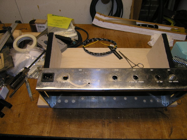
Power cord socket
Since this amp was so messed up to begin with I’m not concerned about making such alterations. I’m also considering making the speaker cable removable.


