Voltage issue corrected
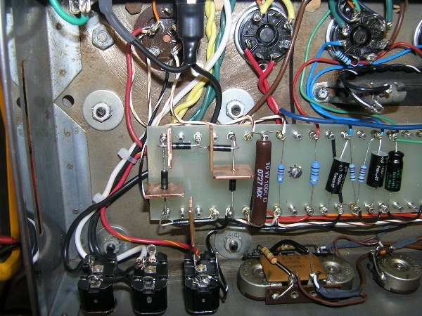
I finally got around to addressing the high voltages I was showing in my amp. After considering a few potential fixes (some internal and some external) I decided on a relatively cheap and simple internal solution involving the use of Zener diodes (1N5347BG’s) in the PT secondary center tap lead to reduce the B+ voltage.
Since I had room at the end of my turret board, I opted to use five 10v, 5w Zener diodes to drop the voltage. I used 1/16″ slugs of copper, 3/4″ square, as heat sinks for each diode. I get a voltage drop of 38.4v across the string of Zeners, which has brought my other voltages much closer to where they should be. Here is a chart showing the voltages I was measuring before and after the fix:
Categories: Ampeg B15NC Project

Congratulations.
FANTASTIC job !!!!
There does not seem to be a thing that you do that the word QUALITY can’t be attached to.
Keith – thank you for the kind words, they mean a lot to me. I had hoped to learn something from this project, which I have. However, it’s also made me realize how much I don’t know! I have received priceless guidance from you and another electronics whiz, David Gauthier. The two of you are not only knowledgeable with the electronics but you both also seem to know the “right” way to do things, rather than just the cheap and easy way. I appreciate the fact that there are people out there with the knowledge and patience to help people like me learn!
I’m a little late finding this site but I’ve enjoyed your account a great deal as I have often dreamed of attempting a similar project myself but lack confidence (and cash) to start.
I did read that hum can be caused from the heater wires (obviously) but the writer went to great pains to get very tight twisted feed wires.He did this by clamping the two wires at one end in a vise and securing the other pair of ends in a hand drill chuck and spun away until the resulting cord was nice and tight (and a thing of beauty). He then he parked cord as far away from any signal wire as he could i.e. tuck up in the corner of the chassis. It would apply to the display light bulb leads as well.
Thanks for all the schematics, ideas and great photos. most entertaining and inspiring great job.